FEATURES OF Drivers

Simple Design
Simple Design

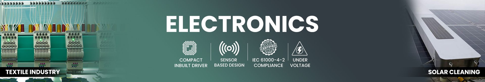
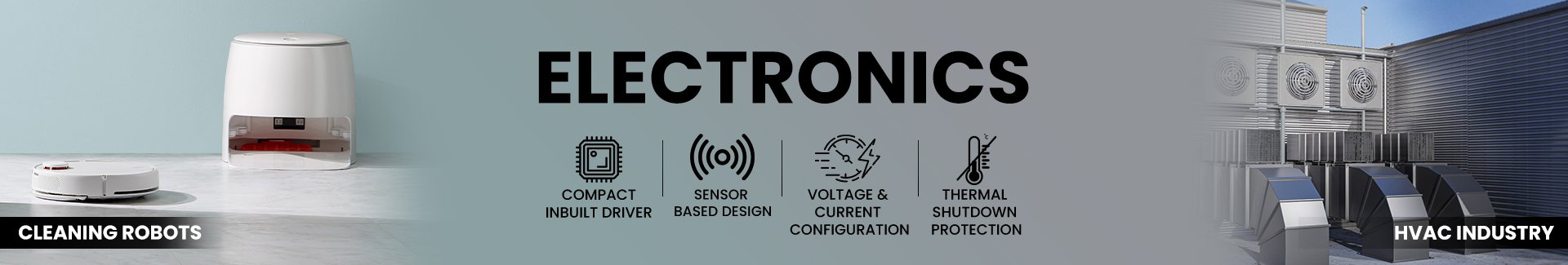
Enhanced portability and provide efficient operation for optimal performance of application

Voltage and Current Configuration

Provide Precise control, optimized power distribution, and enhanced efficiency for superior motor performance

Thermal Shutdown Protection

Ensures safety and reliability by preventing overheating and potential damage during operation

IEC 61000-4-2 Compliance

Ensuring Reliable and Stable Performance of Motor

Industries We Served

Textile

Textile

Energy

Energy

Medical

Medical

HVAC System

HVAC System

Banking

Banking

Frequently Asked Questions (FAQs)

The main difference between sensored and sensorless motor drivers is that sensored motor drivers use external sensors (such as Hall effect sensors or encoders) to provide feedback on the rotor position and speed, while sensorless motor drivers estimate the rotor position based on the back-electromotive force (back-EMF) of the motor.
Pulse Width Modulation (PWM) is a method of turning a signal on and off very quickly at a certain rate. By changing how long the signal stays on compared to how long it stays off (called the pulse width), we can control the average power or voltage sent to a device. This lets us have precise control over how much power is used, which reduces wasted energy and allows us to finely control devices like motors, LEDs, or heaters.
Overvoltage protection is a safety feature that protects electronic devices from getting too much voltage. When the voltage goes higher than what the device can handle, the overvoltage protection kicks in to stop the excess voltage from causing damage. It's like a safety barrier that prevents equipment from breaking and keeps everything running smoothly. Different methods can be used to provide this protection, depending on the situation and what's needed.
Hall sensors generate a certain frequency while the motor is operating. This frequency depends on the speed of the motor and the number of pole pairs of the magnet used in the motor. This frequency can be used to calculate the speed of the motor using the given formula. 1) Motor Speed(RPS) = Hall sensor frequency/No. of pole pairs 2) Motor Speed(RPM) = RPS*60

Related Blog

Address

EL-108, Electronic Zone, Mahape TTC Industrial Estate, Navi Mumbai - 400709, Maharashtra India

h

Drivers


Frank Pro

Frank Pro

In Built BLDC Driver

In Built BLDC Driver

Weber Lite

Weber Lite

Weber Pro

Weber Pro

Faraday

This site uses cookies.

Mechtex uses cookies to enhance your browsing experience, analyze site traffic, and improve our services. By continuing to use our website, you consent to our use of cookies. To learn more, read our Privacy Policy.